Simple Graphs
Here we describe how to represent simple graphs in XML format, where every vertex and edge is specified explicitly.
Simple graphs
Our first example is the following simple graph, with five vertices and five edges:
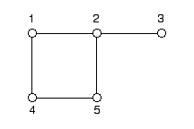
This graph is specified in XML in the following way, where the edges attribute of the <GRAPH> element is optional, since the number of edges can be obtained by counting the number of <EDGE> elements:
<GRAPH vertices="5" edges="5">
<EDGE source="1" target="2"/>
<EDGE source="2" target="3"/>
<EDGE source="1" target="4"/>
<EDGE source="2" target="5"/>
<EDGE source="4" target="5"/>
</GRAPH>
Note that vertices and edges are optional under different conditions. edges is purely informational and does not need to match the actual number of <EDGE> elements. vertices, however, fixes the number of vertices up front, so it can only be left out if every vertex is introduced by an explicit <VERTEX> element — the graph above has none, so its vertices="5" is required, unlike edges="5". More generally, make sure a vertex is already known, either through vertices or an earlier <VERTEX> element, before any <EDGE> refers to it.
Colored graphs
Graphs with colored edges and vertices can also be represented:
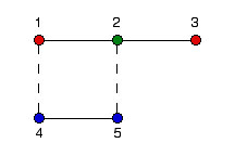
We represent this graph in XML by introducing additional <VERTEX> elements to describe the vertices, and type attributes for vertices and edges to specify their type (color). Vertex types 0,1 and 2 refer to the red, green and blue vertices respectively, while edge types 0 and 1 refer to the solid and dashed lines in our example:
<GRAPH vertices="5" edges="5">
<VERTEX id="1" type="0"/>
<VERTEX id="2" type="1"/>
<VERTEX id="3" type="0"/>
<VERTEX id="4" type="2"/>
<VERTEX id="5" type="2"/>
<EDGE source="1" target="2" type="0"/>
<EDGE source="2" target="3" type="0"/>
<EDGE source="1" target="4" type="1"/>
<EDGE source="2" target="5" type="1"/>
<EDGE source="4" target="5" type="0"/>
</GRAPH>
In this example, the vertices and edges attributes are optional, since both can be obtained by counting the respective number of <VERTEX> and <EDGE> elements.
The optional id attribute of the <VERTEX> element specifies the vertex number. If it is omitted, a consecutive numbering is assumed. The default for the type attribute is 0. A shorter but equivalent version is thus:
<GRAPH>
<VERTEX/>
<VERTEX type="1"/>
<VERTEX/>
<VERTEX type="2"/>
<VERTEX type="2"/>
<EDGE source="1" target="2"/>
<EDGE source="2" target="3"/>
<EDGE source="1" target="4" type="1"/>
<EDGE source="2" target="5" type="1"/>
<EDGE source="4" target="5"/>
</GRAPH>
Coordinates
Use the <COORDINATE> element to specify spatial coordinates for a vertex. Taking the first graph above as an example, the coordinates can be specified as:
<GRAPH vertices="5" edges="5">
<VERTEX id="1"> <COORDINATE> 1 1 </COORDINATE> </VERTEX>
<VERTEX id="2"> <COORDINATE> 2 1 </COORDINATE> </VERTEX>
<VERTEX id="3"> <COORDINATE> 3 1 </COORDINATE> </VERTEX>
<VERTEX id="4"> <COORDINATE> 1 2 </COORDINATE> </VERTEX>
<VERTEX id="5"> <COORDINATE> 2 2 </COORDINATE> </VERTEX>
<EDGE source="1" target="2"/>
<EDGE source="2" target="3"/>
<EDGE source="1" target="4"/>
<EDGE source="2" target="5"/>
<EDGE source="4" target="5"/>
</GRAPH>
In many physics simulations, the system lives on a graph that corresponds to a regular lattice with a unit cell. Within the ALPS framework, it is possible to define such a graph by specifying it in terms of the underlying lattice and unit cell, rather than listing every vertex and edge by hand as we did above. We describe how to do so in the next HOWTO, Lattice and Unit Cells.
For an overview of the rest of this section, see Lattice Definitions. For the LATTICE/GRAPH input parameters used to select a graph in a simulation, see Common Parameters. For the other ALPS documentation sections, see the General Introduction.